The Build
Power Mac G4 AGP Graphics
aka the “Sawtooth”


Now that all that was done, and the system ran as it should, it was time to get on with the exterior dress up.
Honestly, once I had the machine closed up, and
connected to the monitor, keyboard, and other
peripherals, and all tests had passed (and passed
nicely, I might add), I ran it in this condition (no dress
panels) for about 4 months before I started in again.
Anyhow, it’s time to move on to the button up.......
To be continued....

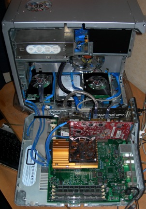
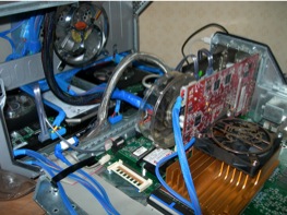
Now that all seems to work, it’s time to put all
of the goodies back in.
Below is a shot of all the internals back where
they belong.
One might note that the case fan tin had the interior blade
guards removed, and a “pretty” one screwed on in its place.
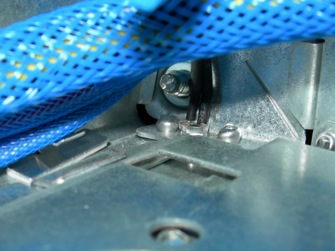
In the picture below, one can see a 5 mm LED inserted into one of the four holes that I mentioned earlier.
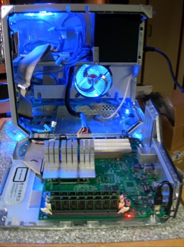
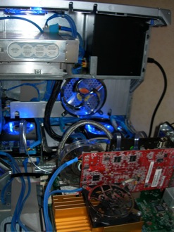
It took me three nights of work to get the wiring done to my satisfaction. In retrospect, it was a real pain in the butt, though I am glad that I went to the trouble.
Once the wiring harness was complete, the PSU, fans, firewire port, USB port, foot lighting, and switches were installed.
From here on out, there is a lot of installing and removing of parts, because I decided to completely rebuild the wiring harness of the 500W PSU. Because of all the hardware planned, I just couldn’t see trying to “get by” with the existing ATX wiring harness
Besides, it needed a bit of “cool” added to it......
______________________________________________________________________________
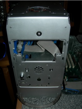
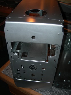
The top of the case was opened to allow mounting of a
80 x 80 x 25 mm case fan to aid ventilation.
The case interior received a 5 mm hole, carefully placed in each of the four bottom corners, to allow a 5 mm LED to illuminate the acrylic feet of the finished machine.
In the rear of the case, a 12 mm hole was placed below the I/O port panel to allow another switch for the lighting effects.
Since I had no intention of using an Airport card, and had
stripped the antenna, I also drilled out the rivets holding the
mounting tin on the interior of the door panel, and removed it.
The case was then de-burred, degreased, and prepped for a
coat of silver paint on the exterior of the case only.
After completely stripping the case, it was prepped
for some new features.
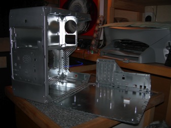
In the front, for an LED light behind the Apple of the
front acrylic panel, a 12 mm hole was opened, to
accommodate a rubber grommet which would hold a
5 mm blue LED backlight.
In the case front, to the left of the power button,
allowing clearance for the power button board
assembly, openings were prepped for a push button
switch (more LED lighting), a firewire port, and a USB
port.
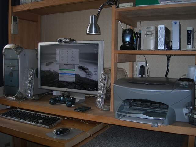
My system as it was before I got the wild idea to tear it apart.......